PROJECTS AND RESEARCH
Some of our projects, from design to validation of the finished part.
Case studies that show how we work: design, FEM analysis, production and lab testing. Where a project comes from research you’ll find peer-reviewed sources to check; where it comes from a commission, we show it in anonymised form.
FROM CAD TO THE LAB
One case, the whole journey
Design, FEM analysis, production, testing and conformity report: the way we work, shown end to end on a certifiable component.
BIOMEDICAL · HORIZON 2020 (MYLEG)
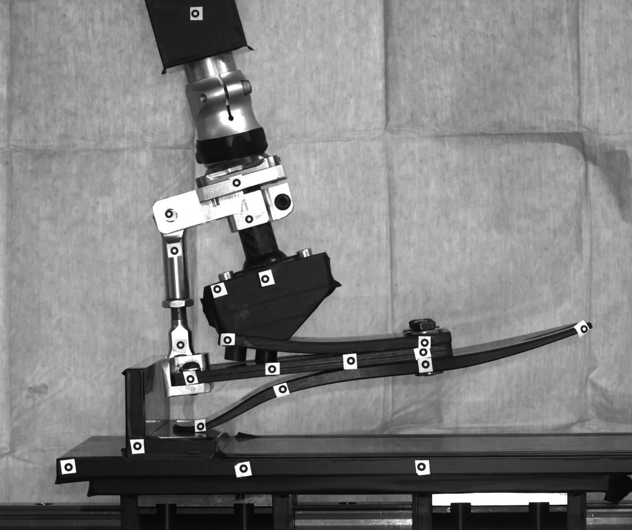
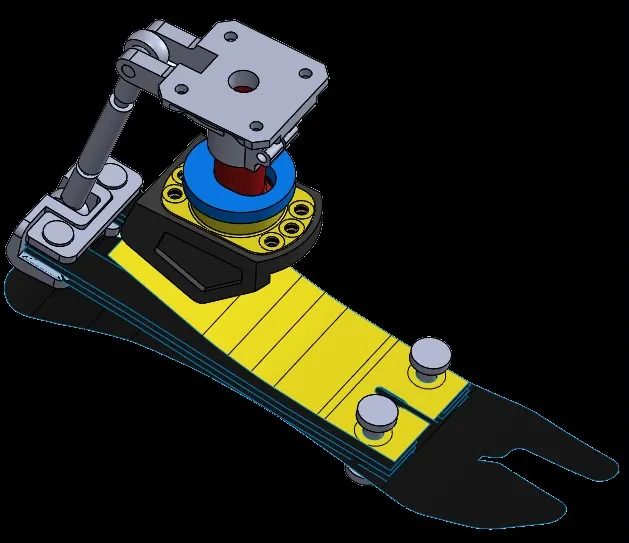
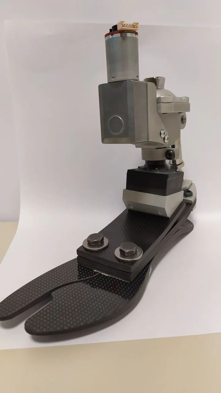
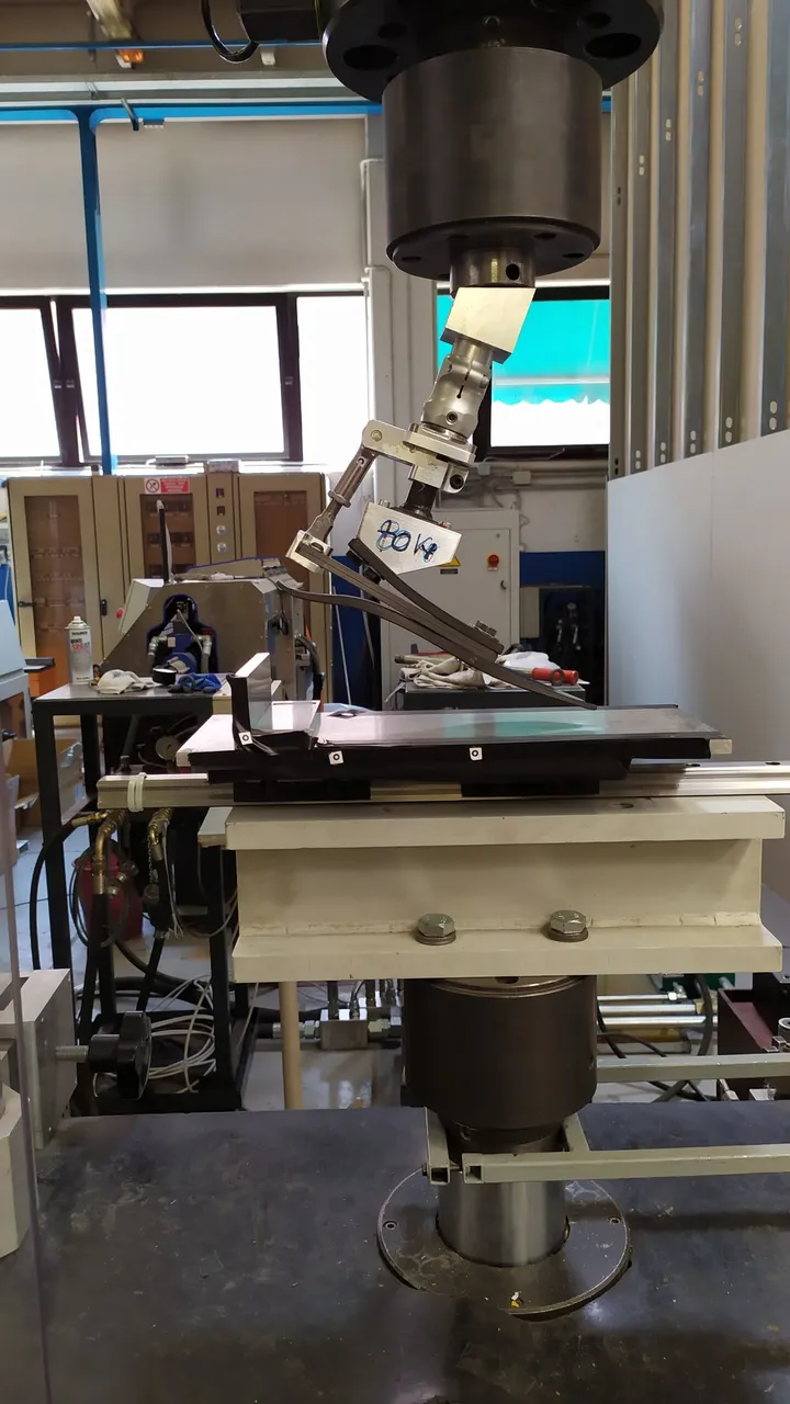
MyFlex-γ: a carbon-fiber foot prosthesis, from design to lab testing
The problem. An ESR foot prosthesis must replicate the rotations of a healthy foot under gait loads, in compliance with ISO 10328. Stiffness depends on geometry and layup together: too many combinations to explore on physical prototypes.
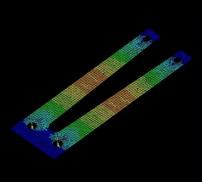
What we did. Within the European MyLeg project (Horizon 2020) we developed a two-level FEM methodology: a fast 2D model for the geometry, a ply-by-ply 3D model for the layup. The carbon prototype, instrumented with sensors, was validated on the bench: static tests to ISO 10328, optical measurements and dynamic verification of the gait cycle (ISO 22675).
- 1,000+ optimization runs
- 45 s per run with the 2D model, vs 4 h for the 3D
- SF 2 at 220% of the category load
- Over 1,000 geometry-optimisation simulations: 45 seconds per run with the 2D model, versus over 4 hours for the equivalent 3D one
- Stiffness curves of the physical prototype matching the FEM model in dorsiflexion
- Safety factor of 2 at 220% of the category load (Tsai-Wu criterion)
- Methodology behind international patent WO2023135510A1
Sources: Applied Sciences 12:97, 2022 (open access) Patent WO2023135510A1
ENGINEERING PROJECTS
From commissions: engineering projects
Work carried out for clients and partners, shown in anonymised form.
AUTOMOTIVE · REVERSE ENGINEERING
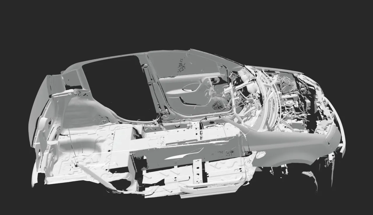
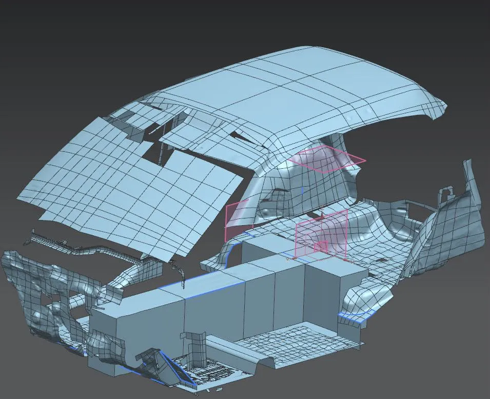
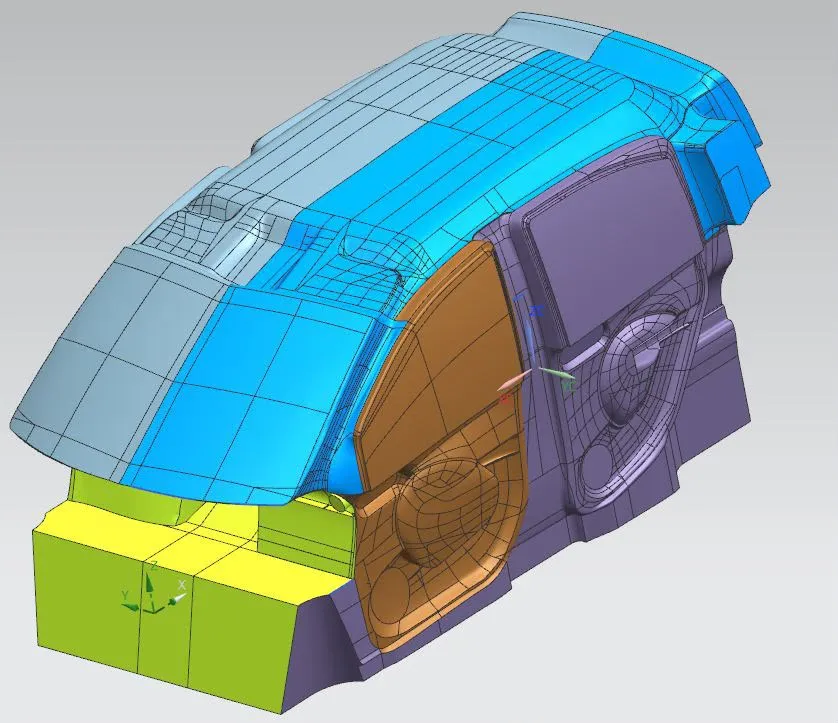
A vehicle converted to electric: from 3D scan to new components
The problem. The vehicle had to switch from combustion to electric propulsion, but there were no CAD models: without the geometry it was impossible to design the new components and check their packaging.
What we did. We scanned the vehicle inside and out and rebuilt body, cabin and individual components in CAD, such as the exhaust manifold. On that geometry we designed the new conversion components, integrating them into the existing spaces.
- Complete scan of exterior, cabin and engine bay
- Body surfaces and components brought back to editable CAD models, in native or STEP format
- New conversion components designed around the vehicle’s real packaging
E-MOBILITY · DESIGN
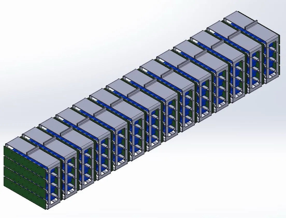
A modular battery pack for an electric vehicle
The problem. A battery pack holds together requirements that contradict each other: energy density, stiffness, electrical connections and maintenance without taking it all apart.
What we did. We designed a repeatable module for cylindrical cells, integrating structure, plates and fixings: the pack is built by repeating the same module, and a fault is fixed by replacing the module, not the pack.
- Modular architecture: one module designed, replicated across the whole pack
- Structure, plates and tie rods sized for assembly and maintenance
- Complete CAD model of the pack, ready for vehicle integration
FROM PUBLISHED RESEARCH
R&D: some of our research and patents
Cases with measured numbers and peer-reviewed sources, from the founders’ research work.
ADVANCED MATERIALS · POR-FESR
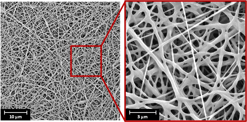
Carbon laminates that damp vibration: +77% with only 1.5% more weight
The problem. Carbon fiber is stiff and light but damps vibration poorly. The classic fix, viscoelastic layers between plies, makes the laminate heavier and cuts its stiffness and strength.
What we did. We interleaved nearly weightless electrospun elastomeric nanofiber membranes between the plies. Damping was measured with cantilever-beam vibration tests; mechanical properties verified with three-point bending and DMA from 20 to 80 °C.
- +77% laminate damping
- +1.5% weight, stiffness and strength unchanged
- +77% laminate damping, with a 1.5% weight increase
- Flexural modulus and strength unchanged at room temperature
- Laminate thickness unchanged versus the reference
Sources: Composite Structures 272, 2021
PRINTING AND CONVERTING · POR-FESR
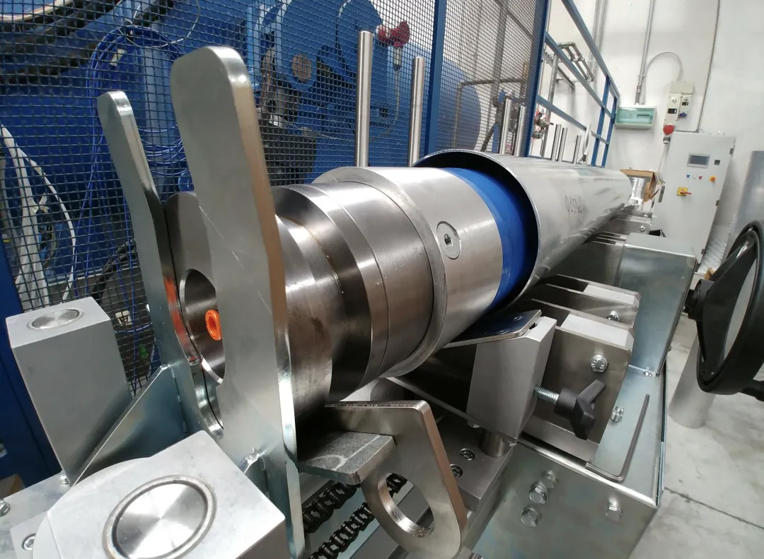
Aluminum-carbon hybrid rollers, co-cured in a single cycle
The problem. Printing machines need rollers that are light and stiff, but with a machinable metal surface. Co-curing carbon inside aluminum is critical: the thermal-expansion mismatch delaminates the interface already on cooling.
What we did. With an Italian roller manufacturer we developed a single-cycle curing process, with an elastomeric interface that redistributes the edge stresses. FEM model validated with strain gauges during curing; layup optimised with design of experiment and a genetic algorithm.
- +30% first natural frequency vs the aluminum tube
- <7% model error on strains measured during cure
- Designed for +30% first natural frequency versus the equivalent aluminum tube
- Model error below 7% (axial) and 4% (hoop) on the strains measured during curing
- Micrographs with no voids and no delamination; the epoxy-interface configuration fails on cooling, as the model predicted
- A design map of the failure index versus diameter and thickness, to size new formats without starting from scratch
Sources: Procedia Structural Integrity 12, 2018 Applied Composite Materials, 2020
MANUFACTURING PROCESSES · COMPOSITES
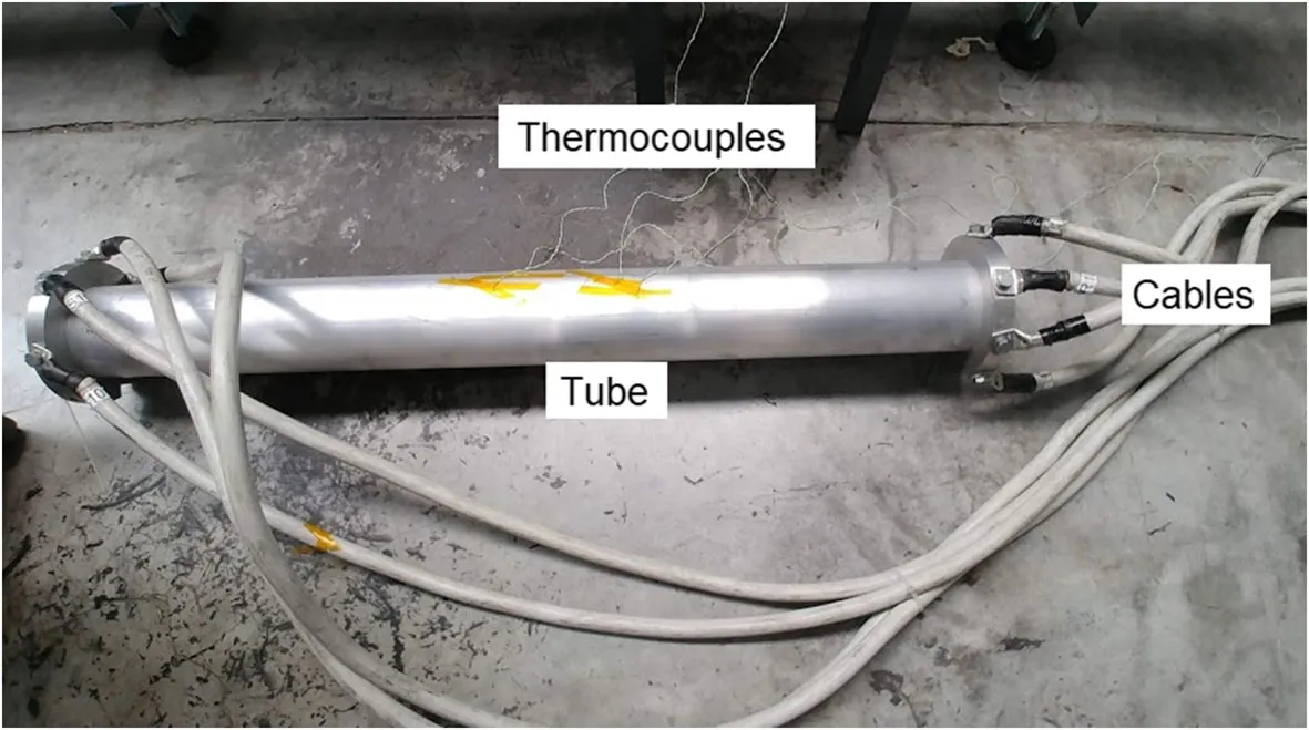
Curing composites without an autoclave: the tube becomes its own oven
The problem. Autoclaves and ovens weigh on costs and energy use, and limit the size of the components you can produce. We needed an alternative able to heat the part uniformly and under control.
What we did. We used the external metal tube as a heating resistor, applying current via the Joule effect with thermocouple feedback control. A thermal model, alongside FEM, predicts the temperature through the thickness and sizes the required current.
- 120 W to cure a 900 mm tube
- <40 Wh/kg energy per kg of part
- <2% thermal model error
- A 900 mm tube cured with about 120 W: less than 40 Wh per kg of component
- Model error below 2% up to the onset of resin crosslinking
- Complete crosslinking confirmed by DSC tests; micrographs with no voids and no delamination
Sources: Applied Composite Materials, 2020
Methods and tools behind these projects
- Nonlinear FEM, contacts and thermal transients
- Optimisation with DOE and genetic algorithms
- Hashin 3D and Tsai-Wu failure criteria
- 3D scanning and surface reconstruction
- Strain gauges, optical measurements and bench testing
- Testing to ISO 10328 / ISO 22675
- DMA and damping measurements
- Micrographs and DSC analysis
- Nanofiber electrospinning
Research projects are documented by verifiable scientific publications; commissioned projects are shown in anonymised form, with no client or partner names. Full confidentiality on drawings and data.
Want to bring this approach to your component?
We design and produce carbon-fiber components and metal-composite hybrids, with the same validation methodology as these projects.
Tell us about your project
Tell us about the component or the problem. We’ll reply with the next steps.